555 Timer Schematic Diagram - 555 Precision Timer Tester Circuit / With this information you will learn how how the 555 works and will have the experience to build some of the circuits below.
byAdmin-
0
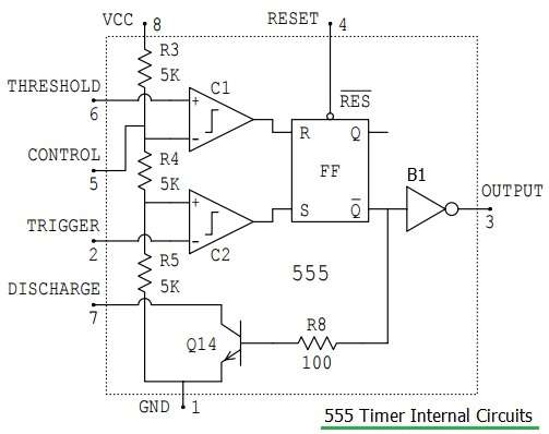
555 Timer Schematic Diagram - 555 Precision Timer Tester Circuit / With this information you will learn how how the 555 works and will have the experience to build some of the circuits below.. Basic 555 monostable multivibrator circuit. In this video we look at a simple 555 astable circuit. Resistive network consists of three equal resistors and acts as a voltage divider. Adjustable on off timer(using 555 astable mode) in this circuit a timer with cyclic on off operations is designed. The 555 timer is a simple integrated circuit that can be used to make many different electronic circuits.
In 2017, it was said over a billion 555 timers are produced. If a 10uf timing capacitor is used, calculate the value of the resistor required to produce a minimum output time delay of 500ms. The 555 timer can be obtained very cheaply from pretty much any electronic retailer. In this mode, the circuit of the ic 555 timer produces the continuous pulses with exact frequency primarily based on the value of the two resistors and. If you want to know all the pinout of the 555 timer, what each pin is and what each pin does, see 555 timer pinout.
Amazing Animation Of Astable Mode Operation Of 555 Timer With Circuit Diagram Funny Electronics from 3.bp.blogspot.com A monostable 555 timer is required to produce a time delay within a circuit. The working modes of a 555 timer are astable, bistable, and monostable. The second 555 timer helper will extend the timers output duration without having to use large values of r1 and/or c1. In this video we look at a simple 555 astable circuit. Adjustable on off timer(using 555 astable mode) in this circuit a timer with cyclic on off operations is designed. Referring to the timing diagram in figure 3, a low voltage pulse applied to the trigger input (pin 2) causes the output voltage at pin 3 to go from low to high. The next diagram shows the basic current consumption of 555 timer chips from different manufacturers. 555 timer circuit circuit diagram from www.circuitdiagram.org and now a full schematic of the 555 timer oscillator with single step and free run option.
In the place of the push switch s1 / trigger switch you can also connect the output of any project to trigger the timer.
555 timer circuit circuit diagram from www.circuitdiagram.org and now a full schematic of the 555 timer oscillator with single step and free run option. The 555 timer ic is an integrated circuit (chip) used in a variety of timer, delay, pulse generation, and oscillator applications. The output voltage from the. In this circuit, after you press the button once, the led will light up then turn off. We can use this property of 555 timer to create various timer circuits like 1 minute timer circuit, 5 minute timer circuit, 10 minute timer circuit, 15 minute timer circuit, etc. A monostable 555 timer is required to produce a time delay within a circuit. Working modes of 555 timer ic. An external triggering is required for transition from stable to unstable state. Figure 2 shows the basic 555 timer monostable circuit. 555 timer, as the name specified, are the electronics circuits used for measuring time intervals.in this article, we will cover about 555 timers. It monitors the charging of the timing capacitor in astable and monostable circuits. 555 one shot timer | circuit diagram. The working modes of a 555 timer are astable, bistable, and monostable.
In this circuit, we will connect the 555 timer to be in astable mode. Simple 555 timer circuits & projects. We have seen in the last few tutorials that the 555 timer can be configured with externally connected components as multivibrators, oscillators and timers, with timing intervals ranging from a few microseconds to many hours. 555 timer is an industrial standard ic existing from early days of ic. With this information you will learn how how the 555 works and will have the experience to build some of the circuits below.
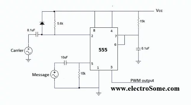
File Pwm Using 555 Timer Circuit Diagram Webp Wikipedia from upload.wikimedia.org Resistive network consists of three equal resistors and acts as a voltage divider. As the name indicates, only one state is stable and the other one is called unstable or quasi stable state. Monostable multivibrator (mmv) mode of 555 timer ic is also called single shot mode. In the place of the push switch s1 / trigger switch you can also connect the output of any project to trigger the timer. 555 datasheet 555 duty cycle 555 metronome 555 reset function 555 time delay relay inverted 555 timer pulse generator. Its name is derived from three 5k ohm resistors ,connected in series used in it.the timer ic can produce required waveform accurately. An external triggering is required for transition from stable to unstable state. 555 timer, as the name specified, are the electronics circuits used for measuring time intervals.in this article, we will cover about 555 timers.
This circuit uses very basic components like 555 timer and 4017 counter.
For 5 min, 10 min and 15 min you just have to change the resistor value (r 1). We can use this property of 555 timer to create various timer circuits like 1 minute timer circuit, 5 minute timer circuit, 10 minute timer circuit, 15 minute timer circuit, etc. In the place of the push switch s1 / trigger switch you can also connect the output of any project to trigger the timer. Additional • timing from microseconds through hours terminals are provided for triggering or resetting if • operates in both astable and monostable modes desired. 555 datasheet 555 duty cycle 555 metronome 555 reset function 555 time delay relay inverted 555 timer pulse generator. Monostable multivibrator (mmv) mode of 555 timer ic is also called single shot mode. Resistive network consists of three equal resistors and acts as a voltage divider. The values of r1 and c1 determine how long the output will remain high. The 555 timer ic is an integrated circuit (chip) used in a variety of timer, delay, pulse generation, and oscillator applications. All we need to change the value of resistor r1 and/or capacitor c1. Use the diagram below to connect the circuit: The 555 timer ic is an integral part of electronics projects. 555 timer circuits (133) browse through a total of 133 555 timer circuits and projects including the timer's datasheet.
The second 555 timer helper will extend the timers output duration without having to use large values of r1 and/or c1. A monostable 555 timer is required to produce a time delay within a circuit. Awesome 555 timer ic projects · 1. If a 10uf timing capacitor is used, calculate the value of the resistor required to produce a minimum output time delay of 500ms. In 2017, it was said over a billion 555 timers are produced.
Arduino Lesson 555 Timer Ic Osoyoo Com from osoyoo.com We would like to show you a description here but the site won't allow us. The breadboard schematic of the above circuit is shown below. Working modes of 555 timer ic. We connect a 100μf capacitor to the positive voltage supply and then to pin 2. Derivatives provide two or four timing circuits in one package.it was commercialized in 1972 by signetics. The block diagram of a 555 timer is shown in the above figure. There are simple circuits for beginners and advanced engineers. If you want to know all the pinout of the 555 timer, what each pin is and what each pin does, see 555 timer pinout.
Basic 555 monostable multivibrator circuit.
We would like to show you a description here but the site won't allow us. Riesige auswahl an cds, vinyl und mp3s. 555 timers are very popular in electronics. The 555 timer starts timing when switched on. Figure 2 shows the basic 555 timer monostable circuit. Basic 555 monostable multivibrator circuit. 555 datasheet 555 duty cycle 555 metronome 555 reset function 555 time delay relay inverted 555 timer pulse generator. All we need to change the value of resistor r1 and/or capacitor c1. 555 timer, as the name specified, are the electronics circuits used for measuring time intervals.in this article, we will cover about 555 timers. We have seen in the last few tutorials that the 555 timer can be configured with externally connected components as multivibrators, oscillators and timers, with timing intervals ranging from a few microseconds to many hours. As the name indicates, only one state is stable and the other one is called unstable or quasi stable state. 555 timer is an industrial standard ic existing from early days of ic. The 555 timer ic is an integrated circuit (chip) used in a variety of timer, delay, pulse generation, and oscillator applications.
This is a 555 one shot timer circuit 555 timer schematic. This is a 555 one shot timer circuit.